Showing posts with label Railways. Show all posts

Monday, 6 May 2024

Leek & Manifold Transport Wagons

Personal modelling has taken a big hit recently with launching a new shop for STModels along with taking the trade stand to Narrow Gauge South. That was an excellent exhibition but being a trader by yourself means virtually no opportunity see round the show so I did a quick run round before the show opened. I was very taken with an Irish layout Fintonagh which has furthered my desire to build a CDR railcar. I think I have all the bits now so it is just a case of getting properly started!

At the show I was asked by a couple of people when am I going to complete the set of transporter cars for the Leek and Manifold Railway. You can already buy the Long Transporter wagon on the new shop here but the short transporters needed their designs finishing. The transporters have quite a history. The first being delivered in 1904, which was actually designed not only to be able to carry standard gauge wagons but to also carry horse drawn carts. History says they were never used for that purpose and were modified fairly quickly.

Then another variant came along in 1907 which was adaptable for two types of wagons, the difference being how low the brake gear hung underneath the wagon. Eventually one of the 1907 wagons was elongated to produce the long transporter wagon used for carrying the 6 wheel milk van.

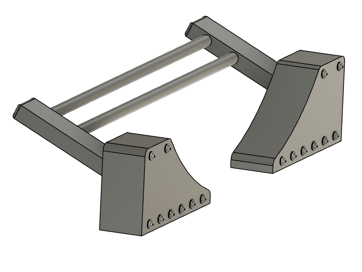
Anyway, a little extra time at home has seen me largely finish the designs. Here they are, almost finished. 


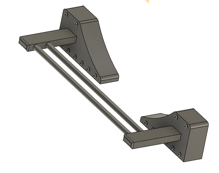
Front right is the 1904 version, front left is the 1907 version with the raised section for taller wagons and at the rear is the long transporter wagon.

The real problem is how to fit wheels beneath them. The wagon only takes a P4 wagon on top and, even then, there isn't enough space underneath to fit a bogie wheelset with outside frames. My friend Matt, for whom the original long transporter was designed, used N gauge pony truck wheels but you have to have a supply of them to make any progress with the wagons.

I therefore took the extra time I have currently and have taught myself how to design an etched brass bogie to go underneath. It's designed to hold the Mosskits 6.2mm diameter wheels. Even then I think it will need the pin points removing from the axles to get full movement.

Here's the design. It's a simple fold up bogie with slots that the axles go into and tabs fold across underneath them to hold the axles in. I've done quite a bit of reading about tolerances and how some items get bigger and some smaller in the etching process so it will be very interesting to see if what I get back conforms to what I expect.

It's not actual modelling for myself but it has been quite fun learning a new skill - watch this space!


Sunday, 7 April 2024

Diema

Ever since attending last year's Welshpool Gala and spending an inordinate amount staring at it in the loop, I have been wondering how to make a model of Diema. At the time I took a good number of photographs just in case I should ever find myself in a position to model it.

In the last Llanfair Journal there was a picture of their works train headed by Diema. The train itself consists of two modified Bowaters Pulp wagons, two RNAD box vans and a Zillertal coach (to be replaced once the Mess Coach has been rebuilt). As it happens I already had my own design for the Bowaters Pulp wagons printed. There are also two RNAD vans in the stash and I have 4 Zillertal coaches so I just need the engine. This is an ideal train for my new roundy roundy (I really must decide on a name) layout.

The biggest problem is a drawing of the engine - it doesn't exist. I asked the team at Welshpool and they don't have a copy either. They did say I could go and measure it but it's a 5 hour drive each way for me. By chance, a good friend, Steve Mann, said he was going for a day trip to Welshpool and foolishly agreed to take some key measurements which would allow me to extrapolate the rest from photos. He excelled himself and now I have most of what I need.

The power unit chosen is from Narrow Japan and came within a week of ordering it. It's a very dinky unit and they do a range of wheelbases and wheel diameters so I expect I will be back for more. I calculated the wheelbase from the centres of the bearings on the photos and the wheel diameter is a best calculation based on the rail height to the centre of the bearings. After that I chose the closest match.

Over the past few days I have designed the body in CAD and have done some basic sizing prints just to get the fundamental dimensions right.


I find myself missing two dimensions:

  1. top of rail to top of footplate
  2. top of rail to bottom of chassis side frame

so those are guesswork for now. It was inevitable that perspective on photos is making some of the calculations harder. The body is sitting a little low but that will be fixed in the next print. For now I will work on what looks right and measure them at the Gala later this year when I am again taking Melin Dolrhyd.

Lastly, here is the basic loco posed next to The Earl to give a sense of size. It is not a tiny diesel!


Tuesday, 6 February 2024

New Year Update

It's been a busy few weeks on the railway front. First it was the SWOONs open day on the Saturday where I had my sales stand for STModels and then it was the annual committee meeting on the Sunday for the 009 Society which, in my role as 009 News Editor, I attend. The following weekend was the regular Wiltshire 009 Group meeting. Then it was the 2 day Southampton show where I was exhibiting Melin Dolrhyd as well as having the STModels sales stand. Last weekend it was the Alton show where I helped operate Garreg Wen for Matt Kean.

All set up and ready for customers at Southampton

STmodels continues to grow and I have done 3 commissions in the past month. The first was for some tank wheels, the second was for some Vale of Rheidol lattice fencing and lastly a request for Southern Railways 8 Wire Concrete fence posts. The last two are available to be bought on STModels.

Southern Railways 8 Wire Concrete posts


The layout with no name has also progressed. It now has the track down, it's wired up and a small amount of scenery has been created. The points are planned to be operated by wire in tube and that has been installed but doesn't show up in the photo. 

Adding the backscene former

The track plan is roughly what was on the initial sketches on the notice board. In the end the actual positioning of the points was dictated by my stock. The points are positioned such that I can have a Bachmann Baldwin and one WD bogie in the headshunt whilst also having 3 WD bogies in the loop and being able to run round them. The section of track between the loop and the running line is long enough to hold a Baldwin without fouling the running line.

The most recent job has been to add the backscene former. This was created with a piece of timber across the back, down the sides and along the bottom to which a piece of 5mm ply was glued. It's added some much needed rigidity to the board. 

The trouble is that it has given me a headache I hadn't envisaged. The layout was planned as something to take to shows that was simple, more easily transportable and more light hearted than Melin Dolrhyd. Keeping it simple was the mantra. The problem is that with it in the railway room against the wall I can't easily reach the point switches. The electrical section switches don't matter as they will always be on. I can just reach the point switches but have a habit of knocking trains off the track. I know I will want to 'play' with the layout and use it to test stock running through the points so it really needs to be useable in the railway room.

The only sensible thing to do is to change the point operation so that it can be operated from the front as well as the back. If I want to extend the mechanical operation in some way then I will have to break up that lovely curved front of the layout, that is if I could work out how to do it!

In the end I have to go back to point motors but I have decided to try servos - this layout was aimed at trying new things, after all. I am currently looking at an Arduino to drive the servos. I had already planned an Arduino Uno to operate a couple of working signals. All this means is I have to extend the system to handle the points as well.

In the stash I have an Arduino Mega, some Dingo servo mounts and some 9g servos. Time for a little experimentation!

Monday, 16 October 2023

Another 3 months between posts!

Oh dear, the number of posts on this blog is definitely going down. Mind you, it is fair to say that a lot has happened in the last 3 months.

We finally moved house in August. We now live in Port Solent, which is a marina complex on the South Coast (well it would be on the coast, wouldn't it) and we are loving it. Here's the view 2 minutes from the house. On a summer's day it is glorious and the sunsets are something else. A kayak is on the buy list for next summer.


I did start my business, STModels, and went to the 009 Open Day in Pewsey and also to the Welshpool Gala where I sold a few items and got the name out there a little. It will never be a big source of income but it was fun and I hope to fill a gap in the market for those who still like to build their own rolling stock. 

As I already mentioned, I took Melin Dolrhyd to the Welshpool Gala, this time with Matt as my second operator. It was an extremely enjoyable few days and I hope to attend next year. Looking ahead, I have confirmed bookings for Melin Dolrhyd for the Southampton show in January and SW Herts show in May. Hopefully there will be more. I am also hoping to take my STModels trade stand to the 009 member's day in Ilton in January.

So what to personal modelling. A new house means a new modelling room. I have taken one of two rooms in the loft conversion for the railway room. There was another option in the house but this room has the best light and does have an 11 foot straight wall. Here's an early days picture as everything was being unpacked (come to think of it, it isn't much tidier 2 months later!).


Of course, nothing works out as expected. I have two bookcases and could only fit one under the eaves so that has reduced the 11ft run. I had expected to keep Melin Dolrhyd up here somewhere but the final stairs to the loft conversion are narrow and I cannot realistically get the main board up them so that has to find a home somewhere else in the house. I really like cameo layouts but they can be bulky and so need more storage and manoeuvring space.

In terms of actual modelling I have 2 areas of focus going forwards. The first is engines. Another good friend, Andy, has built my two Golden Arrow chassis for the Welshpool Beyer Peacocks, they now need finishing ahead of the next show. I also have a Sir Drefaldwyn, and another Sierra Leone locomotive to build. Joan also needs a rebuild and detailing. There may be another Welshpool preservation engine in the stash that I have forgotten but that's enough to be going on with! 

The second area of focus is a new layout. Here's where the big problem lies. What do I do next? I had planned an Ashover based layout. I have a long term plan to do a Bowaters based layout and I am keen to do another Welshpool layout. The problem is that the motivation isn't there at this time to start something that uses multiple boards and handbuilt track and has a high degree of authenticity. Modelling something realistic takes time, a lot of it and I am just not enthused by the idea.

I recently went to the Hayling Light Railway 20th Gala and they had a small model railway exhibition where I saw an 009 layout that was a small roundy roundy layout which offered the potential to be a single board layout that can be chucked in the back of the car and taken to shows. It won't run most of my stock but it will run my Baldwins which were ready for Ashover and I do have a surprising number of 009 Society kits of RNAD vans and Hudson Toastrack coaches that can be quickly built and used. 

It's going to be a complete anathema to what I would normally do but has the advantage of being able to be done relatively quickly. The rough plan is going to be something like this which will allow a train to run round whilst some shunting takes place.


It's not realistic, how could it be with those curves on either side, but it will offer the opportunity to try a few things, play trains, and generally not take modelling too seriously over the winter. 

I need to get on with it. I no longer have a garage and all woodwork needs to be done in the car port which will only get colder so timber was bought and cut this last week and a start has been made. Even though it is supposed to be a quick layout on a 4' by 2' board, I still couldn't bring myself to have a straight front!


I have no idea for a name so answers on a postcard please!

Sunday, 26 March 2023

More Wagon Details

My good friend, Matt, is embarking on an epic Leek & Manifold (L&M) tale. As is the way with these things, there is much planning and even more stock building. Along the way has been a few requests for bits and pieces such as axle boxes and springs for the coach bogies as well as seats for the coaches.

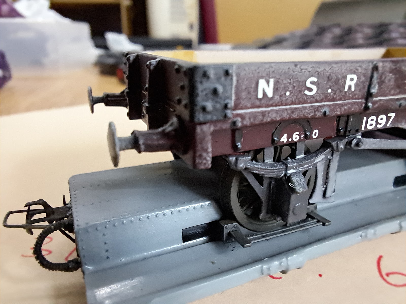
His attention has now moved onto the transporter wagons. Having built the transporter wagons he needs suitable standard gauge wagons to be transported and this is where another good friend, Simon, comes in. He has produced a beautiful North Staffs open wagon and, as is Simon's way, it's to P4 gauge (necessary in this case in order to fit the transporter wagon) and it runs perfectly - so perfectly that it rolls straight off the transporter wagon.

In real life the standard gauge wagons all had hand brakes but the L&M also provided an arrangement of a pair of chocks connected by a pair of rods. These appeared to be of a variety of designs but the reality is that they were probably hand made so differed considerably. I've produced two versions. The first has the side bar protruding horizontally


The second has the side bar protruding up at an angle in order to clear a fold up girder that existed on the transporter wagons as part of handling standard gauge milk tank wagons.

As always, the pictures of the period are unclear and dimensions have to be guessed at. The method of locking the assembly onto the transporter wagon appears to consist of some vertical pieces of metal that slot into the wagon frame but these have not been modelled for simplicity. Here's a cruelly large photo of one of the chocks in place.


All in all it took 3 test prints and then one final print of the numbers that Matt wanted. Each print run takes less than an hour so it's less than a day's work to produce something that can be repeated on demand.

Interestingly, I did try the abs-like resin for this but I found the long thin rods required much more support than the usual resin so I settled on using my normal low odour resin to avoid countless support pips having to be removed.


Sunday, 5 February 2023

Wagon Roofs

Time for a more normal post about building models rather than computer gizmos! 

Currently I have a batch of Welshpool & Llanfair Light Railway (WLLR) wagons in various states. Some were kits I built but hadn't finished. Others were found on the 009 Society second hand stall. The one thing they have in common is that they are unfinished. It's par for the course for me but they need to get done. I've commissioned a complete set of WLLR wagon transfers from Custom Model Decals. When I say complete, I mean only the ones from the Cambrian era and none of that Great Western stuff!

Unfortunately, in looking at these wagons it made me go and look at the ones I had finished and I knew I could do better. When I built the original wagons I did so with speed so that I could have something to run and get a feeling of achievement. Looking at them now there were some obvious things to fix. The first was the plastic handrails (well actually plastic blobs where handrails should be) and the second was the roofs.

Roofs are interesting in that how you model them depends on your view of weathering. Are you a person who models when rolling stock was new and in pristine condition, at the other end of life when all was dilapidated and worn out, or somewhere in-between. For a long time I have modelled in the pristine condition but I have been experimenting with light weathering. 

Most of my wagons have been weathered using AK Weathering Pencils. These are useful items, allowing you to crayon on the weathering and, if you get it wrong, just wipe it off with a damp finger. They are okay for using on roofs but not ideal and nothing I tried was particularly realistic.

Photo courtesy of Brian Webber/ Welshpool & Llanfair Light Railway

Recently I came across the above picture from The Llanfair Railway Journal. It shows one of the Pickering coaches part way through a deep clean. For some reason the original owners of the WLLR decided to paint the roofs of their stock white. It makes no sense really. Railways were dirty environments but maybe there was some reason I am not aware of.

Needless to say, roofs get dirty. All they do is sit outside in all weathers or are pulled behind locomotives that belch out soot and smoke. That has to land somewhere and usually it is on the roofs of vehicles behind. This is only one small view, and I wonder what the rest of the roof was like, but it is interesting to see how uniform is the greyness.

The question is then how best to recreate this in model form. I've had a few different attempts but the following is the technique that seems to be simplest for me to do and produces a reasonable result.

A brief aside is that for many years all my models were painted using spray cans from Halfords or Humbrol acrylics. I've a few paints from other manufacturers like Games Workshop but have always fallen back on good old Humbrol. Recently, I had cause to try some Vallejo paints after watching someone get very good results with them. I have to say I was hooked. The texture of the paints is excellent. Vallejo paints seem to be creamier and hold the paint particles in suspension better than Humbrol. The two paints used on the roofs are, therefore, Vallejo.


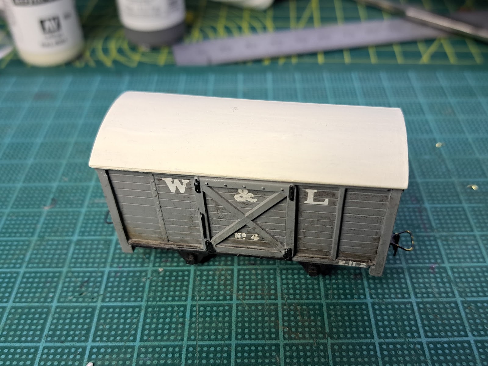
Firstly, I paint the roof in Ivory (70.918). For the effect I wanted to create, there was always going to be glimmers of the original roof colour coming through. It's hard to know from the black and white pictures just how white the original roofs were but we can assume if was fairly bright white. I thought that on a small model, using brilliant white would make it seem more plasticky so settled on ivory. This needs to be allowed to properly dry. For some people this would be 24 hours but I am happy to move onto the next stage after 30 minutes. 


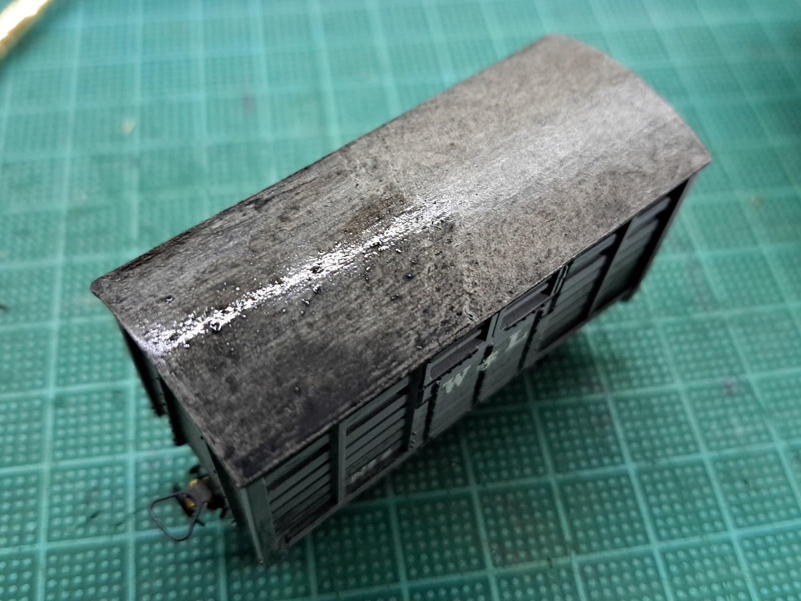
After the coat of Ivory, I use some Dark Grey Wash (76.517). This gets sloshed on. Don't forget to do the edge of the roof as well. The great thing about acrylic washes is that whilst they are wet you can wipe them off with a damp cloth. If you get some where you shouldn't, removal is relatively simple.


The next stage is to dab the wash off with a tissue or piece of kitchen paper. I happened to have some tissue lying on the bench so just picked it up and used it. In the picture above, the far half of the wagon roof has been dabbed, while the near half is waiting to be done. I use the same area of the tissue. I don't use a different area for each dab as that would probably remove too much of the wash. As you dab away the roof becomes a uniform, but mottled, colour. It's the mottling that I was looking to achieve. Again, let this dry and then repeat as many times as you want to do create the depth of weathering you are looking for.

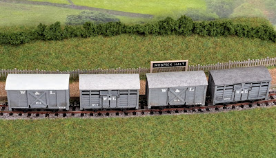
Here are four WLLR wagons. From left to right they are

  1. Plain roof in Ivory
  2. After 1 wash
  3. After 2 washes
  4. After 3 washes

It's likely that on faster lines the weathering would have a streaky feel to it but on a slow backwater like the WLLR I suspect it will be more from the soot falling onto the roofs so the dabbing technique works well. At this point I could take the weathering pencils to the roof and create some more effects but this will do me for now.

I haven't made my mind up how much weathering I want on my wagons. I usually say to people that Melin Dolrhyd is set around 1912. This was a sweet spot in the history of the line when the coaches were plain green and they had converted some of the open wagons to sheep wagons. Recently, I have been looking at the three etched coach kits and thinking it is time to build these in the earlier bronze and white livery which would potentially mean lighter weathering. On reflection, that is overthinking it. I will simply pick which colour I find most pleasing!


Friday, 27 January 2023

Computers and Model Railways

No, I'm not converting the layout to DCC! The layout ran well at Maidenhead with the exception of the two oldest locomotives. My model of "Earl" and my friend's model of "Countess" were not happy with the 12" radius points. "Earl" would fight its way through the points but "Countess" would only operate on the straight track. this is due to them being 20+ years old and using wheels with deep flanges which hit the check rails on the curves. "Earl" was able to go further since it has flangeless centre drivers. Combined with the deep wheels are the outside frames which mean there is no scope for opening the back to back of them. This, hopefully, isn't the end of the world as I have replacements for "Earl" and "Countess" which are planned to be built in the coming months and they will use modern wheel sets. If that fails then I will have to resort to mainline points which are 18" radius but I hope not to go there since that will reduce the length of the sidings by 4" overall.

The only problems encountered at Maidenhead was operator error on setting the points with the occasional stutter over the frogs. The stuttering will be sorted with point motors with frog switches. In my last post I mentioned I was short of one MP1 point motor. The estimated delivery of mid December came and went and another good friend, Adrian, offered me one from his secret stash so I bought that and had enough to start.

The next issue was whether I could reduce the operator error? Get better operators would be the correct answer but that would mean I wasn't allowed to operate my own layout! Traditional operation would have a switch for each point which still leaves scope for not setting them correctly. They could be paired up so that each switch operates the corresponding point at the opposite end. That would reduce the errors but was never going to fully eliminate them. One answer was to operate the points using a push button for each track that, when pressed, would change all the necessary points to make that track the running line. It had to be done!

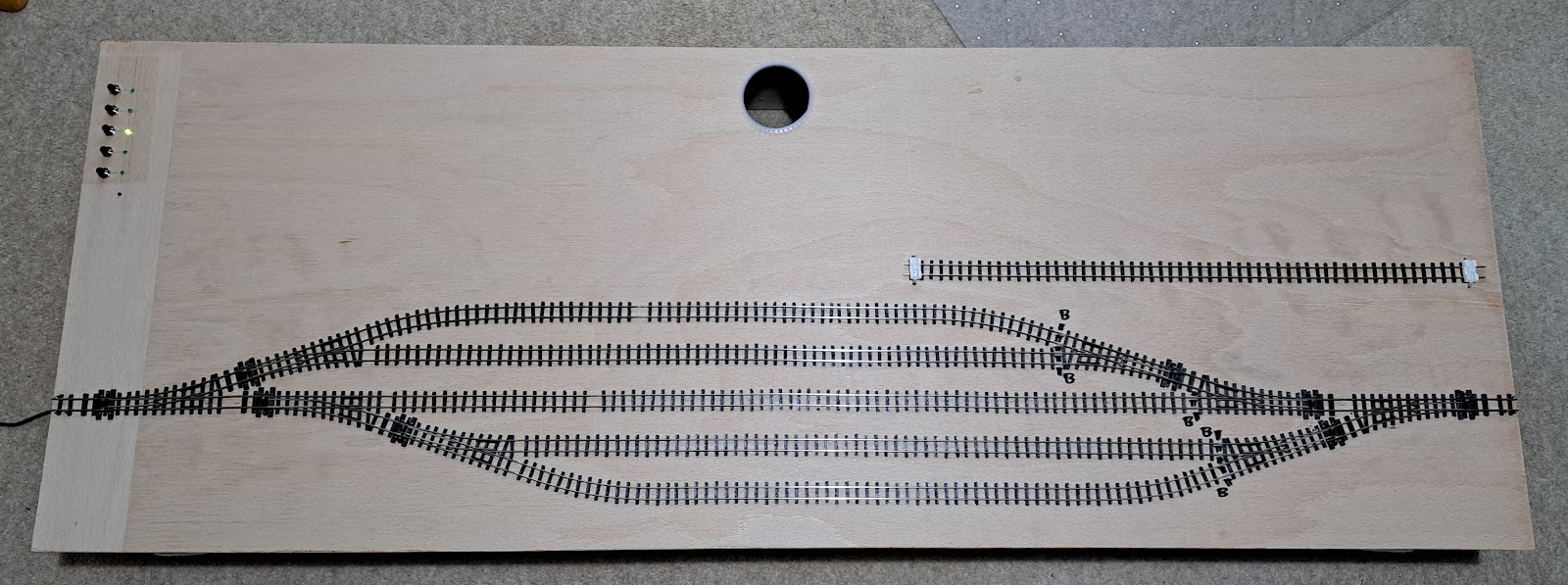
This is the finished result from above.


The five sidings match 5 push button switches top left. This is matched by 5 LEDs next to the switches. The LEDS flash while the points are changing and go solid green when the points are set. The location of the switches is such that when operating the layout from one side (whilst talking to visitors) I can reach them. The is a red LED below the 5 green ones which will flash if something goes wrong and blips every 5 seconds to say the system is working. 

As an aside, have a look at the photo above and tell me where the baseboard side has gone. There is clearly some trick of the light taking place but I cannot see the baseboard side on the edge at the bottom of the picture - weird!

How did I do it, you may well ask. Well let me tell you. I have previously experimented with PIC controllers and briefly considered them but I would need to build a microprocessor board to make it work and the chance of failure would be high. I decided to take a look at the Raspberry Pi and Arduino group of educational systems. These are prebuilt microcontroller boards for which there are a variety of accessory cards, meaning there would be little extra circuitry to wire up. I didn't look too closely at the Raspberry Pi as when I looked at the Arduino it seemed to be ideal for the job.


Pictured above is the Arduino Uno by Keyestudio, wired up and fixed under the fiddle yard. The standard Uno features 14 digital input/output pins and 6 analog input pins. I also picked up the next variant, the Mega, which has many more inputs and outputs. The nice thing about these microcontrollers is that they use a standard USB connector to hook up to the computer, an off the shelf  9V power supply and they are programmed in 'C'. 'C; is the programming language I used most in my career, along with assembly language, so I felt at home straight away. The reality was that writing a program to flash the light on the PCB took me all of 10 minutes. 


Once the microcontroller was decided on then I needed a way to drive the point motors. I bought a solid state relay board but then discovered that it could only switch mains AC so that went back. Instead, I bought an Elegoo 8 channel relay board, shown above. The wiring is a neat ribbon cable to the Arduino and the relays have screw terminals to drive the point motors. The photograph above shows the board with one point motor still to be wired up.

It might be at this point that those of a less nerdy disposition should skip the next few paragraphs down to the photo of the point motor.


What remained was to connect the switches and the LEDs to the Arduino. The LEDs are simply driven from the remaining digital outputs (8 are used for the relays) They need a resistor inline to limit the customer so I used a small piece of strip board shown above. At this point I had run out of the digital inputs/outputs. I could have used the Arduino Mega but as there were unused analog inputs I used those. All it took was a pullup resistor on each input and each switch forces the respective input to zero.

The program was written in Arduino's latest Interactive Development Environment. After the initialisation sequence, the program looks for switch presses and changes the points accordingly. the biggest headache was considering how swiftly to change the point motors. I've got a 2A 9V supply driving the system which is more than enough to drive all point motors at once. However, every time a point motor changes, there will be a spike on the supply as the relay switches and as the point motor kicks in. It is theoretically possible that having all point motors go at once could cause a spike on the microcontroller. Separate power supplies for the motors compared to the microcontroller would help but this is an overkill. All I did was put a 0.2 second delay between each point motor change. This will mean there is a series of smaller spikes over the time taken for all point motors to change.

In order to simplify the brain cells required to understand the program I have two constants in the program, STRAIGHT and CURVED. These apply to the point movement. I also set the standard that the normally closed contacts on the relay card drive the points to the STRAIGHT direction. 

The startup sequence is also interesting. If you configure the point motor input/outputs as outputs then the outputs are immediately driven low which causes all the relays to fire at once. I discovered that you can write the outputs high before you configure them and this value is latched internally and used on configuration so none of the relays fire on power up.

The power up issue still occurs if the points are left in random positions when you turn the power off. Thankfully there can never be all the points in the CURVED way at once. Whilst each switch only changes the minimum number of points needed to achieve the goal of a particular track, the switch for the middle track drives all the points to the STRAIGHT position so it can also serve as an end of day switch to put everything to a known state.

I did put in a 6th LED which blips every 5 seconds just to say the system is still working. It will also flash more vigorously if it gets a weird input from the switches but I realised I wrote the software in such a way that it doesn't look for anything other than the 5 individual switch presses.


The point motors themselves were mounted on a small square of 9mm ply using M2.5 screws as shown above. I wired in each point motor and then held it roughly in place and fired it in both directions to find the optimum place. Once satisfied, I drew round the block of ply and used the hot glue gun to stick the block to the underside of the baseboard. Once done, I felt the position wasn't optimal. The rod that drives the point was hard against the point at each face. The MP1s have an adjustable throw and I had set them all to the smallest one, 3mm, but it was still too much. Peco points have a throw of just over 2mm. I solved this by removing the point motor and using two pieces of 9mm ply instead of just the one. This meant there was some slop at each end but the point always moves. If you ever get the position wrong, the MP1 has adjustments in all 3 dimensions. It really is a clever piece of kit.

With a computer controlled system like this, you do have to ask yourself what you would do if it went wrong. If it isn't a simple wire falling out then the "at an exhibition" option is to drop out the point motors (most of them you can just drop out the control rod) and also disconnect the frog wires. At that point it reverts to the manual operation that was used at Maidenhead.

There it is. Approximately £40 of expenditure and a few extra hours to wire it up and debug the program. It gets its first outing at the Basingstoke show in March - a 2 day show that will give it a good test!

And to cap it all. I finished the fiddle yard yesterday and within an hour I got n email saying my MP1 point motors, ordered in November, have finally shipped!

Saturday, 19 November 2022

Relaying the track

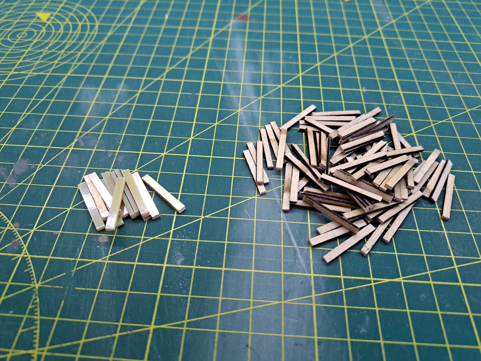
After removing all the old ballast and track I then had to carefully remove any leftover impact adhesive from the old track. Once that was removed it was a case of smoothing it off with a wooden block and some medium grade sandpaper and it was ready to go.

Then it was a case of cutting up the sleepers with a razor saw. The early Cartwright and Russel book on the WLLR states that the sleepers were 6' x 9" x 4.5" at 3' spacing. That meant they should be 24mm on the model but as the track gauge is 1mm smaller than it should be, I decided to cut them to 23mm to keep the visible ratio correct. I used a razor saw and the wooden ones were easy but the fibreglas ones were hard work. Thankfully I only needed 6 - two at each end and two at the track join.


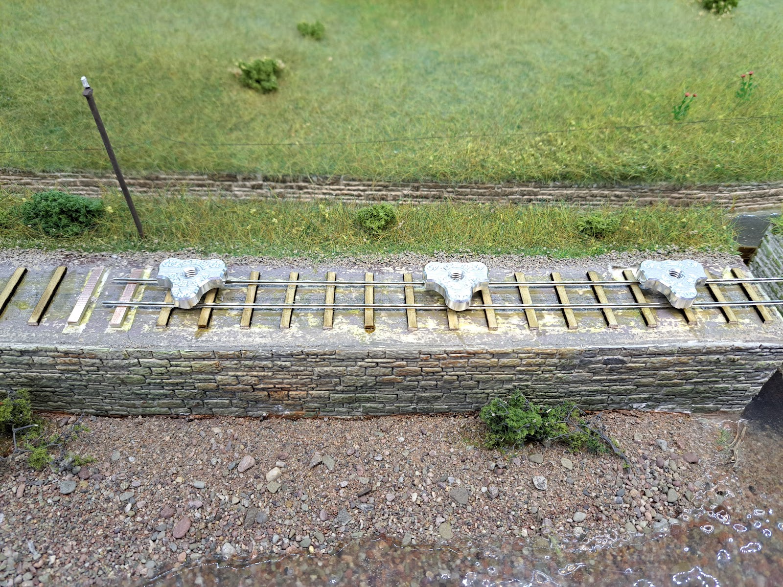
I then went over the trackbed and marked out 12mm spacing and a line of where the far rail should be. the expectation was that I would lay the far rail first and then lay the second rail spaced off that. The first rail was glued to the sleepers with impact adhesive, doing around 12 sleepers worth a time. Once glued and aligned it was weighted down with a metal block.


  After that the second rail could be glued down and spaced off the first rail using the 3 point gauges which were themselves held down with the metal block. Again, I could do about 12 sleepers at a time, and chose to leave the weight on for around an hour before moving to the next section.


Eventually, once it was all down, I just had to solder the track to the copper clad strip, reconnect the wires and run the first train.


The impact adhesive is a messy way of laying track and I am not sure I would continue to do it the same way for a larger layout. that said, it was all made a lot harder by being an afterthough and having to work within the fascia.

Onto the ballasting, a job that very few people like...


Wednesday, 16 November 2022

Time for a refresh

When I was exhibiting Melin Dolrhyd at the Welshpool Gala this year, I was very taken with Martyn Harrison's Castle Caereinion - see the post http://going-loco.blogspot.com/2022/09/return-to-welshpool.html What I really liked was his code 40 track and how it gave a much more light railway feel to the layout. Peco crazy track is excellent for building reliable track quickly but there is no getting away from how chunky it is.

There were really two questions to solve:

  • Would my stock run over it?
  • Was it worth the effort?

To satisfy the first question I had to first obtain some track and also obtain some track gauges. I ordered some code 40 rail from the 2mm Association and some track gauges from FastTracks in the U.S. I already had some suitable sleeper material from the 3mm Society. Once I had all the parts I built a short test track on foamboard. I already had a similar test track with Peco crazy track and was able to compare the two.


Peco on the left and scratchbuilt code 40 on the right. The difference between the two is huge! The track is simply stuck down to the wooden sleepers using impact adhesive. In real life the WLLR pinned the track down. There were no chairs. I was able to run all my stock along the track and none of them bounced on the sleepers, not even the oldest engine in the fleet.

That leaves the question of whether it is worth it. I came away from the Welshpool Gala energised by the show but dissatisfied with the operation of Melin Dolrhyd. The front of the layout was fine but the traverser was not as successful as I had expected. Much of this can be put down to having to make a 4ft traverser fit in a space which is just over 4' 3" long. There were packing pieces and packing pieces and the traverser never seemed to be level across all the tracks. Derailments were more frequent than they should have been for what is essentially a straight piece of track. The traverser is an excellent piece of kit but is overkill on Melin Dolrhyd and suffers from the curse of being a modification to an original design which didn't plan for it.

Taking on board my dissatisfaction with the running I decided it was worth the effort of replacing the track on the front along with replacing the traverser on the back. I'll cover the rear of the layout in another post.

Once the decision was made, I ordered some 1m lengths of track from C&L Finescale along with some roller gauge and they arrived on Friday. I popped across to the 3mm Society West Byfleet meeting on Saturday to pick up some deeper sleeper material which meant I had all the materials necessary to start, so start I did.


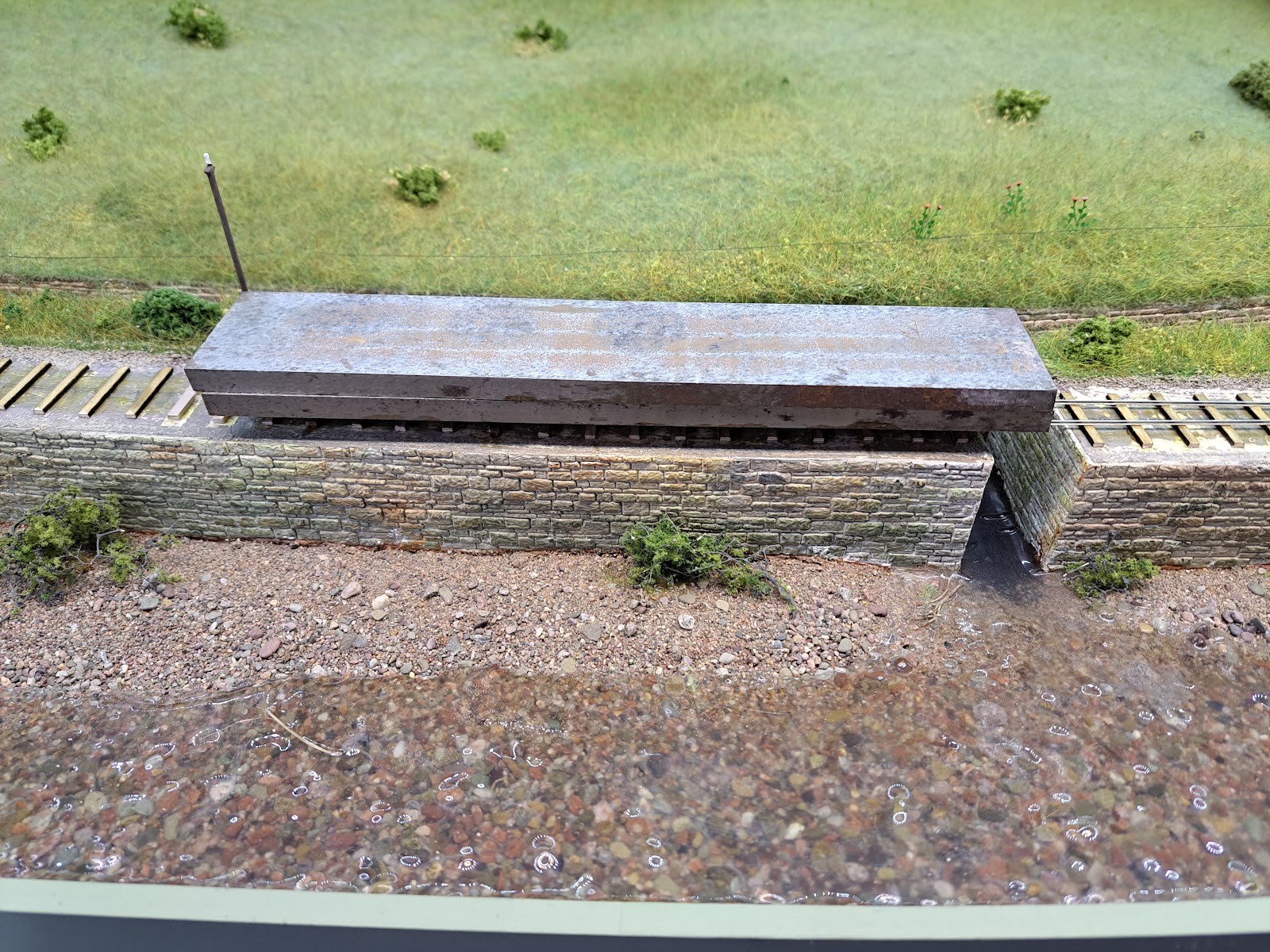
The ballast had been stuck down with the usual pva mix and the track itself was originally stuck down with impact adhesive. I used a dropper to wet the track and then worked away at the ballast with the screwdriver I use for almost every task where I don't use a scalpel. The track itself lifted relatively easily. The track bed is foamboard so I was worried that the card cover would soak and tear off, but it has stayed so far.


In fact it all came off quite easily with the exception of one of the baseboard joins where the card did tear off. In the next post I'll cover preparing it all and laying the track.


Saturday, 5 November 2022

A Little Bit of Publicity

 At the 009 Society local group meeting last weekend I was indebted to one of the members, Derek, who pointed out that Melin Dolrhyd was featured inside the recently published issue of Narrow Gauge World and there is also a photo of Melin Dolrhyd on the cover.


It's not a magazine I usually look at so I was very grateful for the heads up. The article covers the Welshpool Gala and the presence of three Welshpool themed layouts at the Gala. Andrew Charman did the photos and has taken a pleasing angle of the layout with an original train. I'm not sure where the words came from but they do remind me I need to get on and build the engines I have waiting for the layout.

Sunday, 16 October 2022

Coaches 2, 3 and 4

Why the strange title? Very simply, back in April this year I posted that I had completed the first of 4 Ashover coaches. Now I can say that I have almost finished the rest.


The main tasks done since the last update is the lining has been finished on them all. After I took forever to line one side of a coach, my good firend Matt Kean offered to line the rest and finished them off over several evenings - something that would have taken me a few weeks.

I also had to make the rest of the roofs. These are 10 thou brass, 0.35mm brass wire soldered on for rain strips and my own 3D designed and printed torpedo vents glued on. The roofs are simply sprayed with Halfords grey primer and then liberally coated in Humbrol dark grey wash which is then dabbed off with kitchen paper.

Lastly, I glazed all the coaches. This was a tedious job. I found some old Wills packets that had suitable clear plastic that wasn't scratched or cloudy. This was cut into strips (and it is tough to cut) and then stuck in with Kristal Klear. I like using Kristal Klear because it isn't runny and if it gets onto the visible part of the glazing (and it always does), it can be teased away with a cocktail stick as it dries into a rubbery consistency. The first coach took well over the hour but by the time I was onto the last one I had it down to 40 minutes. There is a lot to be said for doing tasks in bulk.


Here's a close-up of coach number 2. The roof isn't stuck down as I need to add some people. There is one last job to do which is to fettle the bogies. When I test ran the coaches round Melin Dolrhyd I discovered that they didn't get round the 12" curves without derailing. Unfortunately I had not been sufficiently careful when assembling the bracke stanchion with the result that they angle inwards limiting the amount of swing on the bogies.

The goal is to get these really finished this week ahead of starting a major update to Melin Dolryhd. More on that when the post man delivers the necessary bits!

Thursday, 8 September 2022

Return to Welshpool

That was an excellent weekend at the Welshpool & Llanfair Gala. The trains were good, the models were good and the company was excellent. Melin Dolrhyd provoked much discussion about the state of the mill now and how it looks a bit of a mess compared to the idyllic scene I have created. Martin Rich did an excellent job of looking after us and provisionally I have an invite to return next year.

There were some excellent other narrow gauge layouts there as well. the layout that interested me most was Martyn Harrison's "Castle Caereinion". What caught my attention the most was the hand built track using Code 40 rail from the 2mm Association. It seriously makes me think about replacing the track on Melin Dolrhyd. After all I only have a 4' 3" stretch of plain track to change...

The other item that caught me thinking about what else I need to do is that my model of Joan is undetailed and looks very poor compared to Martyn's version. I know I did mine quickly as spare stock for the layout but it is time to revisit it.

The layout on the other side of me was Peter Cullen's "Welford Coppice" - a small quarry layout that includes both OO and OO9. Very well modelled.


Mark Holland's "Spirit of Welshpool" was also in attendance supported by the Sussex Downs 009 Group. Having walked through Welshpool on Saturday morning on my way to breakfast I can attest that he has captured the essence of the railway.


Blair Hobson's "Ostrovia" was also there. This is an HOe layout which runs stock from different countries over the day.


To round off the 009 Society presence, we had Julien Webb and Steve Mann from the West Midlands Narrow Gauge Group flying the flag, modelling, talking and encouraging people to join.


There were layouts in other scales but I didn't photograph them all. Dave Gauntlet of "Banwy Models" had a small display case showing his various 3D prints whcih look superb. I already have 2 bolster wagons from him partially finished.

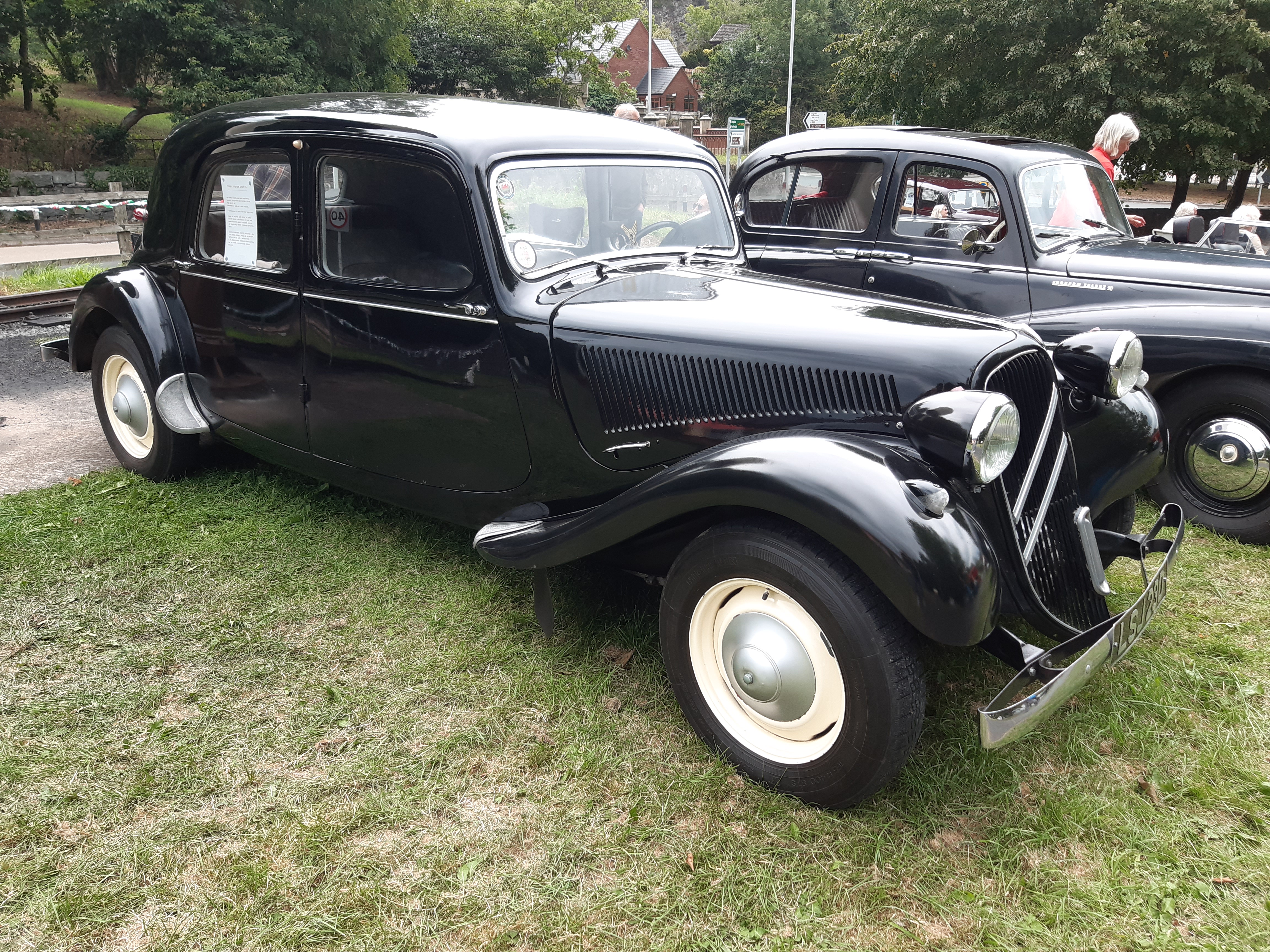
Outside the shed the trains were running and there were busses, classic cars and various steam vehicles. Below is a taste of some of the items of transport that were around over the Gala Weekend including "Premier" from the Sittingbourne and Kemsley Light Railway which I finally managed to see at 5pm on the Sunday!


Leek & Manifold Transport Wagons

Personal modelling has taken a big hit recently with launching a new shop for STModels along with taking the trade stand to Narrow Gauge Sou...