Monday 16 October 2023

Another 3 months between posts!

Oh dear, the number of posts on this blog is definitely going down. Mind you, it is fair to say that a lot has happened in the last 3 months.

We finally moved house in August. We now live in Port Solent, which is a marina complex on the South Coast (well it would be on the coast, wouldn't it) and we are loving it. Here's the view 2 minutes from the house. On a summer's day it is glorious and the sunsets are something else. A kayak is on the buy list for next summer.


I did start my business, STModels, and went to the 009 Open Day in Pewsey and also to the Welshpool Gala where I sold a few items and got the name out there a little. It will never be a big source of income but it was fun and I hope to fill a gap in the market for those who still like to build their own rolling stock. 

As I already mentioned, I took Melin Dolrhyd to the Welshpool Gala, this time with Matt as my second operator. It was an extremely enjoyable few days and I hope to attend next year. Looking ahead, I have confirmed bookings for Melin Dolrhyd for the Southampton show in January and SW Herts show in May. Hopefully there will be more. I am also hoping to take my STModels trade stand to the 009 member's day in Ilton in January.

So what to personal modelling. A new house means a new modelling room. I have taken one of two rooms in the loft conversion for the railway room. There was another option in the house but this room has the best light and does have an 11 foot straight wall. Here's an early days picture as everything was being unpacked (come to think of it, it isn't much tidier 2 months later!).


Of course, nothing works out as expected. I have two bookcases and could only fit one under the eaves so that has reduced the 11ft run. I had expected to keep Melin Dolrhyd up here somewhere but the final stairs to the loft conversion are narrow and I cannot realistically get the main board up them so that has to find a home somewhere else in the house. I really like cameo layouts but they can be bulky and so need more storage and manoeuvring space.

In terms of actual modelling I have 2 areas of focus going forwards. The first is engines. Another good friend, Andy, has built my two Golden Arrow chassis for the Welshpool Beyer Peacocks, they now need finishing ahead of the next show. I also have a Sir Drefaldwyn, and another Sierra Leone locomotive to build. Joan also needs a rebuild and detailing. There may be another Welshpool preservation engine in the stash that I have forgotten but that's enough to be going on with! 

The second area of focus is a new layout. Here's where the big problem lies. What do I do next? I had planned an Ashover based layout. I have a long term plan to do a Bowaters based layout and I am keen to do another Welshpool layout. The problem is that the motivation isn't there at this time to start something that uses multiple boards and handbuilt track and has a high degree of authenticity. Modelling something realistic takes time, a lot of it and I am just not enthused by the idea.

I recently went to the Hayling Light Railway 20th Gala and they had a small model railway exhibition where I saw an 009 layout that was a small roundy roundy layout which offered the potential to be a single board layout that can be chucked in the back of the car and taken to shows. It won't run most of my stock but it will run my Baldwins which were ready for Ashover and I do have a surprising number of 009 Society kits of RNAD vans and Hudson Toastrack coaches that can be quickly built and used. 

It's going to be a complete anathema to what I would normally do but has the advantage of being able to be done relatively quickly. The rough plan is going to be something like this which will allow a train to run round whilst some shunting takes place.


It's not realistic, how could it be with those curves on either side, but it will offer the opportunity to try a few things, play trains, and generally not take modelling too seriously over the winter. 

I need to get on with it. I no longer have a garage and all woodwork needs to be done in the car port which will only get colder so timber was bought and cut this last week and a start has been made. Even though it is supposed to be a quick layout on a 4' by 2' board, I still couldn't bring myself to have a straight front!


I have no idea for a name so answers on a postcard please!

Saturday 22 July 2023

New Venture - STModels

It's been 3 months since the last post. What have I been doing? The simple answer is very little modelling mainly brought on by other activities. 

I have two major activities currently ongoing. The first is moving house. We kicked this off in February and had hoped to have moved by now but it is still ongoing. Every room of the house has been gone through and unwanted/unused items have gone to other homes - that includes all the stuff I brought with me, just in case I need them, at the last move 9 years ago that I have not used - lesson to learn!

The second activity is I have been wanting to start my own business for quite a while and I now feel that my design skills are at the level where I can produce reliable parts that other people will find useful. To that end I can now announce that STModels is open for business. I am primarily focusing on the after detailing market but also have a range of general purpose items.

The biggest collection of items is for the Welshpool & Llanfair Light Railway (WLLR), with the emphasis on helping the modeller complete the Worsley Works coaches and refurbish old Nine Lines wagon kits. For the coaches there are detailing kits that contain seats, vacuum cylinder, oil lamps and torpedo vents. There is also a roof in development as well as bogies to be able to make a complete coach. For the wagons, there are replacement solebars, brake levers, guards foot boards and brake shoes allowing the modeller to update as little or as much as they want. All these items are targeted at 4mm modelling. Obviously some of these items can be used for other railway lines.


The second biggest collection of items are general items such as milk churns, steel drums, barrels, pallets, etc. These items are available in several scales - 2mm (N), 2.5mm (TT:120), 3mm, 3.5mm (HO) and 4mm (OO). The nice thing about producing items in multiple scales is that if you want something smaller to go in the background to help force perspective or simply because space is tight then you can buy a smaller size right now.


Other ranges include items for the Vale of Rheidol and Leek and Manifold railways. Only the former is on the website as it takes time to prepare an item for production. If you have items that you want to see produced then please contact me through the website and I will see what can be achieved.

Not only can you buy online using Paypal, you can buy in person, in 2 weeks time on Sat 5th August, at the 009 Wiltshire Group Day (see https://009society.com/news/exhibitions-events/) where I will have a stand and I will aim to have as many items as possible available for you to see and purchase. I am also planning to take the stand to the Welshpool Gala (see https://wllr.org.uk/) on 1st to 3rd September.

Please bookmark the website and, if you are on Facebook, please like my Facebook page at https://www.facebook.com/STModels3D which is where most announcements will take place. If it makes sense then I will add a mailing list in the future.

Let me know if you see anything wrong. I am still taking photographs and adding them to the site but decided now is the right time to go public. Wish me luck!

Saturday 8 April 2023

Refurbishing Old Wagons

I'm currently embarked on an exercise of getting some old Nine Lines Welshpool wagons ready for transfers and have also been looking closely at the detail and running qualities of my existing wagons. Several of my existing wagons do not run well. Van number 4 is a prime example. It used to sway sideways when running. Some of it was down to the wheels which were old and eccentric but some of it was down to bearing holes that were worn out.

The quick solution would be to drill (at a slight angle) and fit bearings but a close look at the underside of the wagon shows how crude is the original solebar and W Iron mould. I don't know if this has been improved now the range has been taken over by N-Drive Productions but I saw a challenge I wanted to meet. 

You can see the W Iron on the picture below. It's just a flat piece of moulding.


The solebars easily came off using some blunt nosed pliers and I was able to apply myself to designing a replacement solebar. The book "The Welshpool & Llanfair Light Railway" by Glyn Williams has some very good drawings that are hopefully reasonably accurate. They allowed me to create the following item.


It took a few versions but eventually I got an assembly I was happy with. The solebars are recessed to take the Dundas DP09 Bearings though the holes need drilling out. Getting resin to drain from horizontal holes is a real challenge! There's two versions, one with the brake lever bracket and one without.

Here's a picture of the van with the new solebars before painting.


The next stage was to design and print the brake lever and brake shoe. These wagons literally only had one brake shoe. Again, after a few versions I got to the right shape. Here is a picture of the van before painting the lever and shoe.


Finally, here is the finished version, all painted.


With the bearings and the latest Dundas/Mosskito wheels it runs a treat. Mind you, having looked at the photograph more closely I realise that I have forgotten the works and wagon plates but I designed and printed those a long time ago so it won't take long to resolve.

I now have a range of parts for refurbishing my other wagons so I guess I need to get my skates on and update them all. The big question for me is whether there is a market out there for these types of refurbishment kits. 


Sunday 26 March 2023

More Wagon Details

My good friend, Matt, is embarking on an epic Leek & Manifold (L&M) tale. As is the way with these things, there is much planning and even more stock building. Along the way has been a few requests for bits and pieces such as axle boxes and springs for the coach bogies as well as seats for the coaches.

His attention has now moved onto the transporter wagons. Having built the transporter wagons he needs suitable standard gauge wagons to be transported and this is where another good friend, Simon, comes in. He has produced a beautiful North Staffs open wagon and, as is Simon's way, it's to P4 gauge (necessary in this case in order to fit the transporter wagon) and it runs perfectly - so perfectly that it rolls straight off the transporter wagon.

In real life the standard gauge wagons all had hand brakes but the L&M also provided an arrangement of a pair of chocks connected by a pair of rods. These appeared to be of a variety of designs but the reality is that they were probably hand made so differed considerably. I've produced two versions. The first has the side bar protruding horizontally


The second has the side bar protruding up at an angle in order to clear a fold up girder that existed on the transporter wagons as part of handling standard gauge milk tank wagons.

As always, the pictures of the period are unclear and dimensions have to be guessed at. The method of locking the assembly onto the transporter wagon appears to consist of some vertical pieces of metal that slot into the wagon frame but these have not been modelled for simplicity. Here's a cruelly large photo of one of the chocks in place.


All in all it took 3 test prints and then one final print of the numbers that Matt wanted. Each print run takes less than an hour so it's less than a day's work to produce something that can be repeated on demand.

Interestingly, I did try the abs-like resin for this but I found the long thin rods required much more support than the usual resin so I settled on using my normal low odour resin to avoid countless support pips having to be removed.


Wednesday 22 March 2023

Printing Wagon Details

Another piece of work over the last few weeks has been designing and printing some wagon details. 

I am finishing off some wagons pending transfers. In the process I am adding bearings to allow the stock to run more freely. This has sometimes necessitated cutting off the solebar to allow the bearings to be fitted and the solebars to go back on slightly further apart. This isn't an issue since 009 track is technically 1mm narrower than it should be for the Welshpool & Llanfair, so could be argued that it is putting the solebar back to the correct dimensions... 

The process of removing the solebar did result in damage to the brake lever and the brake shoe. Looking around at how to replace them, I did consider the easy way of buying them but couldn't be sure that any on the market were of the correct length. That led me to deciding to print them. 

Looking at the open wagon page in the Glyn Williams book revealed a couple of points I had previously missed. The first is that the brake lever doesn't lie flat against the solebar as I had been modelling them. It actually comes out at a fairly steep angle to the edge of the wagon. The second point I had missed is that the brake lever assembly is fixed to the wagon by a bracket that comes out from under the wagon and up the side of it.

It would make a complicated part but could it be printed?

This is what I was able to come up with. It has a thick spigot at the back of the ratchet assembly. this provides a good surface to glue the assembly onto the wagon. More importantly, it helps it hold a vertical shape.

The piece of the bracket that comes out from under the wagon is very fine and I had to put a fine cut out in the inside right angle to prevent resin pooling there that would prevent it sitting flat on the wagon. the part is far too fragile to cut or file.


The photo suffers from being blown up horribly but it's clear it can be printed and, once glued onto the wagon, is pretty strong.

I used a different resin for this print. Talking to someone demonstrating at the Southampton show recently, I learnt that he uses an abs-like resin for final prints as this is less brittle so more tolerant of  knocks. I decided this would be a good part on which to try such a resin as it is a very vulnerable part, likely to get damaged with handling. The real drawback to abs-like resin is that it is not available in a low odour form so really does smell.

I know I am taking 3D printing to the limit here. On a few of the levers it managed to print the gap in the ratchet part of the assembly, despite being only 0.4mm wide.


The ones for the vans will have to be done at some point but this has pointed the way to a plentiful source of replacements. Then there is the brake shoes...


Saturday 18 March 2023

Basingstoke Show

Last weekend was the Basingstoke Show and I took Melin Dolrhyd. The new fiddle yard worked really well and my fellow operator declared that he liked it which is good from someone who prefers to keep their distance from technology.


It's a very friendly show with a range of layouts and traders, though I understand that several traders dropped out on the day which is frustrating for the organisers and anyone who was coming specifically for those traders.

Sadly, "The Earl" failed to get going. The first hour of a show is always fraught with locos warming up and generally getting into a rhythm. "The Earl" never got into a rhythm. It stuttered it's way round the layout and no cleaning or fettling of pickups was making any difference so it was immediately retired and will have to be overhauled to get back into operation. It is over 30 years old and was made by the late Rod Alcock so it's fair for it to want some attention.

It meant that Dennis, from the Snailbeach Railway was called into service for the two days. I clearly need a couple more engines to ensure the layout only runs engines that have run on the WLLR.

The other noticeable issue was some of the stock on some of the points. There were a few derailments in the fiddle yard. One particular point was very noticeable.


When I got the layout home I set it up again in the lounge and ran stock in a variety of directions. Above is the point that was giving most trouble. As you can see, there is a huge offset on the join between the blade and the fixed rail. When going through the point from the toe, stock was hitting that join and the lighter wagons were bouncing off.

There was also a track offset between two boards which surprised me due to the number of alignment dowels and the track being soldered at the ends. It didn't cause any issues but I have now corrected it so that it shouldn't cause and issues in the future.

I have also embarked on an exercise of checking track and wheel geometry as well as coupling heights. Anything one can do to bring consistency has to help with good running. Thankfully, nearly all the problems occurred in the fiddle yard. The front of the layout was fine.

There were two other narrow gauge layouts at the show. The first was one the Basingstoke Group were refurbishing that they had obtained second hand. The second was "Sandy Shores" by Jamie Warne. This can best be described as a small sand dune shunting layout. It won the Chairman's Choice trophy. Jamie has kindly sent through some photos which are reproduced here. You can also follow his blog here.


Saturday 11 February 2023

Wagon Handrails

Warning - cruel photography alert!

Another task awaiting me is adding handrails. As I said in the last post, I did the wagons with speed which meant several compromises, the most obvious being leaving on the plastic lumps that represented handrails. It's time to remove those and replace them with more representative wire.

Conventional wisdom is to use brass rod of around 0.33mm diameter so this is what I did. The handrails on the brake van are an interesting shape. In real life they screw onto the side of the van facing into the opening and then turn outwards to make it easier for the guard to grab them. On the model the only way to fix handrails onto the model is to actually glue them into holes in the model. This makes for another bend in the handrail.


The picture above shows the handrails quite cleanly. It took me several goes with the finest snipe nosed pliers to get the bends close enough to each other.

Here's another closer, very cruel, shot which shows that after painting the handrails are becoming quite chunky. I can't find the diameter of the real handrails anywhere but 0.33mm is 1" in real life. Add in the primer and topcoat then it is getting pretty thick and closer to 1.5"

A search of the internet highlight that 0.3mm rod is available but then the next thickness is 0.2mm. That is small but also offered a challenge. I bought some 0.2mm rod in both nickel silver and brass. I also bought some Tamiya 0.2mm drills. I figured buying just one drill was asking for trouble - they are so small.


In real life, the handle of the covered van appears to be thinner than the brake van handles so I tackled that first. The handle is glued into two holes that were drilled and a small piece of flattened wire was glued on top and bottom to simulate the original fitting.

This is so much finer and I really like it. I used the nickel silver wire just to have some more strength to cope with handling. The question then arose on how best to represent the brake van opening rail. The real thing is fundamentally a hook and eye, but could it be done in 4mm.


The answer is "Yes". I had to wrap the wire round another piece of wire to create the loop and then had to drill the wagon at an angle but that doesn't show. At this point I broke one of the drills so I only managed 3 holes per drill which, at £6 a drill makes the holes very costly.

A decision still needs to be made on what to do. I haven't found any 0.25mm wire rod yet so options are:
  1. Revert to 0.33mm and accept they must be over scale
  2. Try 0.3mm and maybe just use black primer to reduce the number of coats of paint
  3. Carry on with 0.2mm and take the hit on drills
  4. Consider using Metal Black instead of paint

I'm undecided, but if this was Facebook I would do a poll 😃

Sunday 5 February 2023

Wagon Roofs

Time for a more normal post about building models rather than computer gizmos! 

Currently I have a batch of Welshpool & Llanfair Light Railway (WLLR) wagons in various states. Some were kits I built but hadn't finished. Others were found on the 009 Society second hand stall. The one thing they have in common is that they are unfinished. It's par for the course for me but they need to get done. I've commissioned a complete set of WLLR wagon transfers from Custom Model Decals. When I say complete, I mean only the ones from the Cambrian era and none of that Great Western stuff!

Unfortunately, in looking at these wagons it made me go and look at the ones I had finished and I knew I could do better. When I built the original wagons I did so with speed so that I could have something to run and get a feeling of achievement. Looking at them now there were some obvious things to fix. The first was the plastic handrails (well actually plastic blobs where handrails should be) and the second was the roofs.

Roofs are interesting in that how you model them depends on your view of weathering. Are you a person who models when rolling stock was new and in pristine condition, at the other end of life when all was dilapidated and worn out, or somewhere in-between. For a long time I have modelled in the pristine condition but I have been experimenting with light weathering. 

Most of my wagons have been weathered using AK Weathering Pencils. These are useful items, allowing you to crayon on the weathering and, if you get it wrong, just wipe it off with a damp finger. They are okay for using on roofs but not ideal and nothing I tried was particularly realistic.

Photo courtesy of Brian Webber/ Welshpool & Llanfair Light Railway

Recently I came across the above picture from The Llanfair Railway Journal. It shows one of the Pickering coaches part way through a deep clean. For some reason the original owners of the WLLR decided to paint the roofs of their stock white. It makes no sense really. Railways were dirty environments but maybe there was some reason I am not aware of.

Needless to say, roofs get dirty. All they do is sit outside in all weathers or are pulled behind locomotives that belch out soot and smoke. That has to land somewhere and usually it is on the roofs of vehicles behind. This is only one small view, and I wonder what the rest of the roof was like, but it is interesting to see how uniform is the greyness.

The question is then how best to recreate this in model form. I've had a few different attempts but the following is the technique that seems to be simplest for me to do and produces a reasonable result.

A brief aside is that for many years all my models were painted using spray cans from Halfords or Humbrol acrylics. I've a few paints from other manufacturers like Games Workshop but have always fallen back on good old Humbrol. Recently, I had cause to try some Vallejo paints after watching someone get very good results with them. I have to say I was hooked. The texture of the paints is excellent. Vallejo paints seem to be creamier and hold the paint particles in suspension better than Humbrol. The two paints used on the roofs are, therefore, Vallejo.


Firstly, I paint the roof in Ivory (70.918). For the effect I wanted to create, there was always going to be glimmers of the original roof colour coming through. It's hard to know from the black and white pictures just how white the original roofs were but we can assume if was fairly bright white. I thought that on a small model, using brilliant white would make it seem more plasticky so settled on ivory. This needs to be allowed to properly dry. For some people this would be 24 hours but I am happy to move onto the next stage after 30 minutes. 


After the coat of Ivory, I use some Dark Grey Wash (76.517). This gets sloshed on. Don't forget to do the edge of the roof as well. The great thing about acrylic washes is that whilst they are wet you can wipe them off with a damp cloth. If you get some where you shouldn't, removal is relatively simple.


The next stage is to dab the wash off with a tissue or piece of kitchen paper. I happened to have some tissue lying on the bench so just picked it up and used it. In the picture above, the far half of the wagon roof has been dabbed, while the near half is waiting to be done. I use the same area of the tissue. I don't use a different area for each dab as that would probably remove too much of the wash. As you dab away the roof becomes a uniform, but mottled, colour. It's the mottling that I was looking to achieve. Again, let this dry and then repeat as many times as you want to do create the depth of weathering you are looking for.

Here are four WLLR wagons. From left to right they are

  1. Plain roof in Ivory
  2. After 1 wash
  3. After 2 washes
  4. After 3 washes

It's likely that on faster lines the weathering would have a streaky feel to it but on a slow backwater like the WLLR I suspect it will be more from the soot falling onto the roofs so the dabbing technique works well. At this point I could take the weathering pencils to the roof and create some more effects but this will do me for now.

I haven't made my mind up how much weathering I want on my wagons. I usually say to people that Melin Dolrhyd is set around 1912. This was a sweet spot in the history of the line when the coaches were plain green and they had converted some of the open wagons to sheep wagons. Recently, I have been looking at the three etched coach kits and thinking it is time to build these in the earlier bronze and white livery which would potentially mean lighter weathering. On reflection, that is overthinking it. I will simply pick which colour I find most pleasing!


Friday 27 January 2023

Computers and Model Railways

No, I'm not converting the layout to DCC! The layout ran well at Maidenhead with the exception of the two oldest locomotives. My model of "Earl" and my friend's model of "Countess" were not happy with the 12" radius points. "Earl" would fight its way through the points but "Countess" would only operate on the straight track. this is due to them being 20+ years old and using wheels with deep flanges which hit the check rails on the curves. "Earl" was able to go further since it has flangeless centre drivers. Combined with the deep wheels are the outside frames which mean there is no scope for opening the back to back of them. This, hopefully, isn't the end of the world as I have replacements for "Earl" and "Countess" which are planned to be built in the coming months and they will use modern wheel sets. If that fails then I will have to resort to mainline points which are 18" radius but I hope not to go there since that will reduce the length of the sidings by 4" overall.

The only problems encountered at Maidenhead was operator error on setting the points with the occasional stutter over the frogs. The stuttering will be sorted with point motors with frog switches. In my last post I mentioned I was short of one MP1 point motor. The estimated delivery of mid December came and went and another good friend, Adrian, offered me one from his secret stash so I bought that and had enough to start.

The next issue was whether I could reduce the operator error? Get better operators would be the correct answer but that would mean I wasn't allowed to operate my own layout! Traditional operation would have a switch for each point which still leaves scope for not setting them correctly. They could be paired up so that each switch operates the corresponding point at the opposite end. That would reduce the errors but was never going to fully eliminate them. One answer was to operate the points using a push button for each track that, when pressed, would change all the necessary points to make that track the running line. It had to be done!

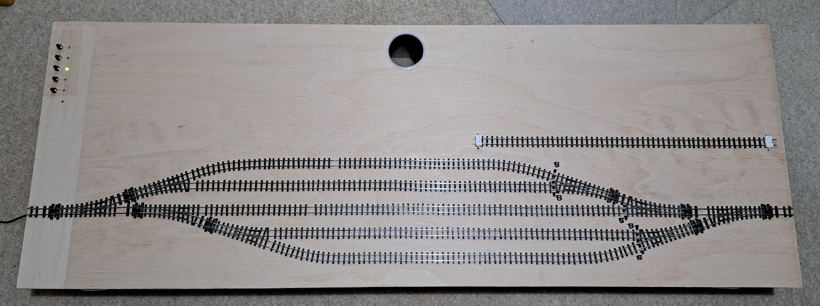
This is the finished result from above.


The five sidings match 5 push button switches top left. This is matched by 5 LEDs next to the switches. The LEDS flash while the points are changing and go solid green when the points are set. The location of the switches is such that when operating the layout from one side (whilst talking to visitors) I can reach them. The is a red LED below the 5 green ones which will flash if something goes wrong and blips every 5 seconds to say the system is working. 

As an aside, have a look at the photo above and tell me where the baseboard side has gone. There is clearly some trick of the light taking place but I cannot see the baseboard side on the edge at the bottom of the picture - weird!

How did I do it, you may well ask. Well let me tell you. I have previously experimented with PIC controllers and briefly considered them but I would need to build a microprocessor board to make it work and the chance of failure would be high. I decided to take a look at the Raspberry Pi and Arduino group of educational systems. These are prebuilt microcontroller boards for which there are a variety of accessory cards, meaning there would be little extra circuitry to wire up. I didn't look too closely at the Raspberry Pi as when I looked at the Arduino it seemed to be ideal for the job.


Pictured above is the Arduino Uno by Keyestudio, wired up and fixed under the fiddle yard. The standard Uno features 14 digital input/output pins and 6 analog input pins. I also picked up the next variant, the Mega, which has many more inputs and outputs. The nice thing about these microcontrollers is that they use a standard USB connector to hook up to the computer, an off the shelf  9V power supply and they are programmed in 'C'. 'C; is the programming language I used most in my career, along with assembly language, so I felt at home straight away. The reality was that writing a program to flash the light on the PCB took me all of 10 minutes. 


Once the microcontroller was decided on then I needed a way to drive the point motors. I bought a solid state relay board but then discovered that it could only switch mains AC so that went back. Instead, I bought an Elegoo 8 channel relay board, shown above. The wiring is a neat ribbon cable to the Arduino and the relays have screw terminals to drive the point motors. The photograph above shows the board with one point motor still to be wired up.

It might be at this point that those of a less nerdy disposition should skip the next few paragraphs down to the photo of the point motor.


What remained was to connect the switches and the LEDs to the Arduino. The LEDs are simply driven from the remaining digital outputs (8 are used for the relays) They need a resistor inline to limit the customer so I used a small piece of strip board shown above. At this point I had run out of the digital inputs/outputs. I could have used the Arduino Mega but as there were unused analog inputs I used those. All it took was a pullup resistor on each input and each switch forces the respective input to zero.

The program was written in Arduino's latest Interactive Development Environment. After the initialisation sequence, the program looks for switch presses and changes the points accordingly. the biggest headache was considering how swiftly to change the point motors. I've got a 2A 9V supply driving the system which is more than enough to drive all point motors at once. However, every time a point motor changes, there will be a spike on the supply as the relay switches and as the point motor kicks in. It is theoretically possible that having all point motors go at once could cause a spike on the microcontroller. Separate power supplies for the motors compared to the microcontroller would help but this is an overkill. All I did was put a 0.2 second delay between each point motor change. This will mean there is a series of smaller spikes over the time taken for all point motors to change.

In order to simplify the brain cells required to understand the program I have two constants in the program, STRAIGHT and CURVED. These apply to the point movement. I also set the standard that the normally closed contacts on the relay card drive the points to the STRAIGHT direction. 

The startup sequence is also interesting. If you configure the point motor input/outputs as outputs then the outputs are immediately driven low which causes all the relays to fire at once. I discovered that you can write the outputs high before you configure them and this value is latched internally and used on configuration so none of the relays fire on power up.

The power up issue still occurs if the points are left in random positions when you turn the power off. Thankfully there can never be all the points in the CURVED way at once. Whilst each switch only changes the minimum number of points needed to achieve the goal of a particular track, the switch for the middle track drives all the points to the STRAIGHT position so it can also serve as an end of day switch to put everything to a known state.

I did put in a 6th LED which blips every 5 seconds just to say the system is still working. It will also flash more vigorously if it gets a weird input from the switches but I realised I wrote the software in such a way that it doesn't look for anything other than the 5 individual switch presses.


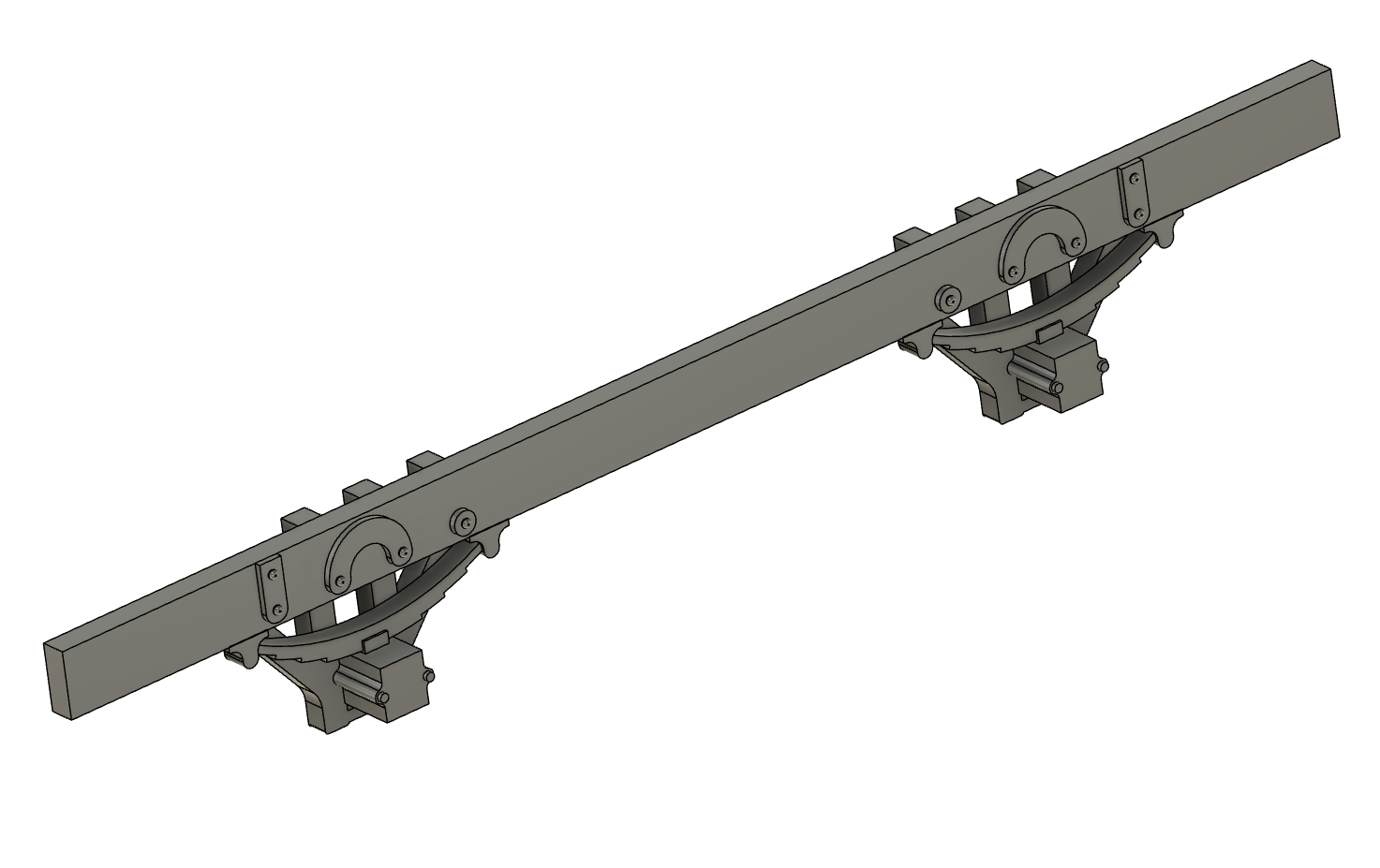
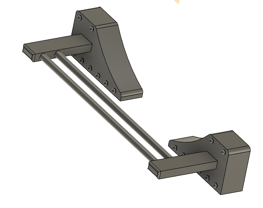
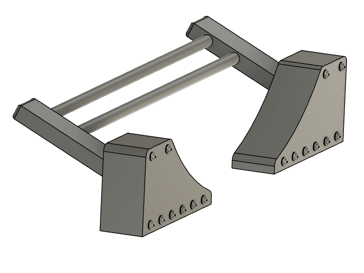
The point motors themselves were mounted on a small square of 9mm ply using M2.5 screws as shown above. I wired in each point motor and then held it roughly in place and fired it in both directions to find the optimum place. Once satisfied, I drew round the block of ply and used the hot glue gun to stick the block to the underside of the baseboard. Once done, I felt the position wasn't optimal. The rod that drives the point was hard against the point at each face. The MP1s have an adjustable throw and I had set them all to the smallest one, 3mm, but it was still too much. Peco points have a throw of just over 2mm. I solved this by removing the point motor and using two pieces of 9mm ply instead of just the one. This meant there was some slop at each end but the point always moves. If you ever get the position wrong, the MP1 has adjustments in all 3 dimensions. It really is a clever piece of kit.

With a computer controlled system like this, you do have to ask yourself what you would do if it went wrong. If it isn't a simple wire falling out then the "at an exhibition" option is to drop out the point motors (most of them you can just drop out the control rod) and also disconnect the frog wires. At that point it reverts to the manual operation that was used at Maidenhead.

There it is. Approximately £40 of expenditure and a few extra hours to wire it up and debug the program. It gets its first outing at the Basingstoke show in March - a 2 day show that will give it a good test!

And to cap it all. I finished the fiddle yard yesterday and within an hour I got n email saying my MP1 point motors, ordered in November, have finally shipped!

Diema

Ever since attending last year's Welshpool Gala and spending an inordinate amount staring at it in the loop, I have been wondering how t...